I want to know if it's possible to connect a ttl device directly to my
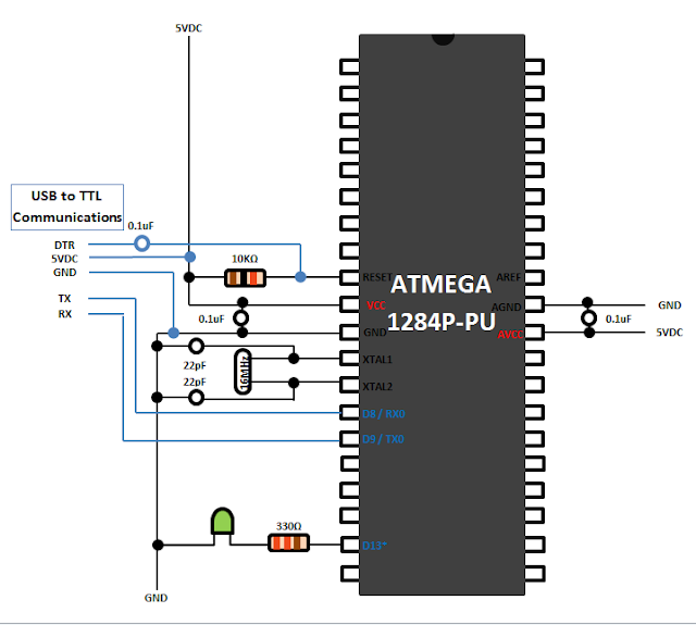
PIC18LF4680 for serial communication via USART . I can connect the ttl device directly to my Arduino Uno without issues.
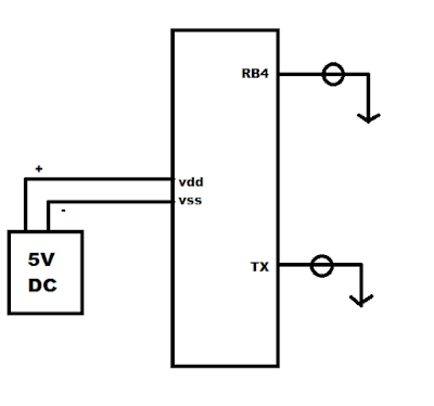
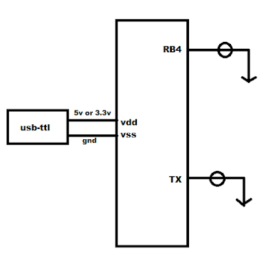
This is my hardware :


The ttl device has 6 pins
(dtr , rxd , txd , vcc(3.3v or 5v) , cts, gnd) .
I have two different codes snippets below that perform USART communication.
Version one(I) utilizes the "usart.h" peripheral library.
Version two(II) uses "TXREG" and "RCREG" for sending and receiving data.
Both versions run well in my virtual environment (proteus 8 professional),
but not in the real world environment. Am I missing a step? Do I need a special
library? Or is it not possible with this chip?
Version I--------------------------------------------------------------------
-------------------------------------------------------------------------------
- Code: Select all
#include "fuses.h"
#include <p18lf4680.h>
#include <stdio.h>
#include <stdlib.h>
#include <plib/usart.h>
void main(void) {
     TRISB = 0x00;
     OSCCON = 0x76; // 8mhz (0111 0110)
     LATBbits.LATB4 = 0;
     LATBbits.LATB1 = 0;
     LATBbits.LATB0 = 0;
     unsigned char txt1[] = "Hello World \r\n";
     unsigned char txt2[] = "Enter a number.... \r\n";

     CloseUSART();

     OpenUSART(USART_TX_INT_OFF &
     USART_RX_INT_OFF &
     USART_ASYNCH_MODE &
     USART_EIGHT_BIT &
     USART_CONT_RX &
     USART_BRGH_HIGH &
     USART_ADDEN_OFF ,
     52);

     for(int x=0;x<=20;x++){__delay_ms(50);}
     // write/send intro to PC

     while(BusyUSART());
     putsUSART((char *)txt1);

     for(int x=0;x<20;x++){__delay_ms(50);}

     while(BusyUSART());
     putsUSART((char *)txt2);

     for(int x=0;x<20;x++){__delay_ms(50);}

     while(1){
        sdata = ReadUSART();
        switch(sdata){
        case '1':
            LATBbits.LATB4 = 1;
            LATBbits.LATB1 = 0;
            LATBbits.LATB0 = 0;
            break;
        case '2':
            LATBbits.LATB4 = 0;
            LATBbits.LATB1 = 1;
            LATBbits.LATB0 = 0;
        break;
        case '3':
            LATBbits.LATB4 = 0;
            LATBbits.LATB1 = 0;
            LATBbits.LATB0 = 1;
        break;
        default:
            LATBbits.LATB4 = 0;
            LATBbits.LATB1 = 0;
            LATBbits.LATB0 = 0;
        break;
        }
     }
}
--------------------------------------------------------------------------
Version II---------------------------------------------------------------
--------------------------------------------------------------------------
- Code: Select all
#include "fuses.h"
#include <p18lf4680.h>
#include <stdio.h>
#include <stdlib.h>
#define STRLEN 12
volatile unsigned char t;
volatile unsigned char rcindex;
volatile unsigned char rcbuf[STRLEN];

void USART_init(void){
     TXSTAbits.TXEN = 1; // enable transmitter
     TXSTAbits.BRGH = 1; // high baud rate mode
     RCSTAbits.CREN = 1; // enable continous receiving

     // configure I/O pins
     TRISCbits.TRISC7 = 1; // RX pin is input
     TRISCbits.TRISC6 = 1; // TX pin is input (automatically configured)
     SPBRG = 52;
     PIE1bits.RCIE = 1; // enable USART receive interrupt
     RCSTAbits.SPEN = 1; // enable USART
}
void USART_putc(unsigned char c)
{
     while (!TXSTAbits.TRMT); // wait until transmit shift register is empty
     TXREG = c; // write character to TXREG and start transmission
}
void USART_puts(unsigned char *s)
{
     while (*s)
     {
          USART_putc(*s); // send character pointed to by s
          s++; // increase pointer location to the next character
     }
}

void main(void) {
     OSCCON = 0x76; // 8mhz (0111 0110)
     USART_init();
     USART_puts("Init complete! \n");
     INTCONbits.PEIE = 1; // enable peripheral interrupts
     INTCONbits.GIE = 1; // enable interrupts
     while(1)
     {
     }
}
void interrupt ISR(void)
{
     if (PIR1bits.RCIF) // check if receive interrupt has fired
     {
            t = RCREG; // read received character to buffer
           // check if received character is not new line character
           // and that maximum string length has not been reached
           if ( (t != '\n') && (rcindex < STRLEN) )
           {
               rcbuf[rcindex] = t; // append received character to string
               rcindex++; // increment string index
           }
           else
           {
               rcindex = 0; // reset string index
               USART_puts(rcbuf); // echo received string
           }
           PIR1bits.RCIF = 0; // reset receive interrupt flag
    }
}
Chip Configurations ("fuses.h") ---------------------------------------------------------------
- Code: Select all
// PIC18LF4680 Configuration Bit Settings
// 'C' source line config statements
// CONFIG1H
#pragma config OSC = IRCIO67 // Oscillator Selection bits (Internal oscillator block, port function on RA6 and RA7)
#pragma config FCMEN = OFF // Fail-Safe Clock Monitor Enable bit (Fail-Safe Clock Monitor disabled)
#pragma config IESO = OFF // Internal/External Oscillator Switchover bit (Oscillator Switchover mode disabled)
// CONFIG2L
#pragma config PWRT = OFF // Power-up Timer Enable bit (PWRT disabled)
#pragma config BOREN = OFF // Brown-out Reset Enable bits (Brown-out Reset disabled in hardware and software)
#pragma config BORV = 3 // Brown-out Reset Voltage bits (VBOR set to 2.1V)
// CONFIG2H
#pragma config WDT = OFF // Watchdog Timer Enable bit (WDT disabled (control is placed on the SWDTEN bit))
#pragma config WDTPS = 32768 // Watchdog Timer Postscale Select bits (1:32768)
// CONFIG3H
#pragma config PBADEN = ON // PORTB A/D Enable bit (PORTB<4:0> pins are configured as analog input channels on Reset)
#pragma config LPT1OSC = OFF // Low-Power Timer 1 Oscillator Enable bit (Timer1 configured for higher power operation)
#pragma config MCLRE = OFF // MCLR Pin Enable bit (RE3 input pin enabled; MCLR disabled)
// CONFIG4L
#pragma config STVREN = ON // Stack Full/Underflow Reset Enable bit (Stack full/underflow will cause Reset)
#pragma config LVP = ON // Single-Supply ICSP Enable bit (Single-Supply ICSP enabled)
#pragma config BBSIZ = 1024 // Boot Block Size Select bits (1K words (2K bytes) Boot Block)
#pragma config XINST = OFF // Extended Instruction Set Enable bit (Instruction set extension and Indexed Addressing mode disabled (Legacy mode))
// CONFIG5L
#pragma config CP0 = OFF // Code Protection bit (Block 0 (000800-003FFFh) not code-protected)
#pragma config CP1 = OFF // Code Protection bit (Block 1 (004000-007FFFh) not code-protected)
#pragma config CP2 = OFF // Code Protection bit (Block 2 (008000-00BFFFh) not code-protected)
#pragma config CP3 = OFF // Code Protection bit (Block 3 (00C000-00FFFFh) not code-protected)
// CONFIG5H
#pragma config CPB = OFF // Boot Block Code Protection bit (Boot block (000000-0007FFh) not code-protected)
#pragma config CPD = OFF // Data EEPROM Code Protection bit (Data EEPROM not code-protected)
// CONFIG6L
#pragma config WRT0 = OFF // Write Protection bit (Block 0 (000800-003FFFh) not write-protected)
#pragma config WRT1 = OFF // Write Protection bit (Block 1 (004000-007FFFh) not write-protected)
#pragma config WRT2 = OFF // Write Protection bit (Block 2 (008000-00BFFFh) not write-protected)
#pragma config WRT3 = OFF // Write Protection bit (Block 3 (00C000-00FFFFh) not write-protected)
// CONFIG6H
#pragma config WRTC = OFF // Configuration Register Write Protection bit (Configuration registers (300000-3000FFh) not write-protected)
#pragma config WRTB = OFF // Boot Block Write Protection bit (Boot block (000000-0007FFh) not write-protected)
#pragma config WRTD = OFF // Data EEPROM Write Protection bit (Data EEPROM not write-protected)
// CONFIG7L
#pragma config EBTR0 = OFF // Table Read Protection bit (Block 0 (000800-003FFFh) not protected from table reads executed in other blocks)
#pragma config EBTR1 = OFF // Table Read Protection bit (Block 1 (004000-007FFFh) not protected from table reads executed in other blocks)
#pragma config EBTR2 = OFF // Table Read Protection bit (Block 2 (008000-00BFFFh) not protected from table reads executed in other blocks)
#pragma config EBTR3 = OFF // Table Read Protection bit (Block 3 (00C000-00FFFFh) not protected from table reads executed in other blocks)
// CONFIG7H
#pragma config EBTRB = OFF // Boot Block Table Read Protection bit (Boot block (000000-0007FFh) not protected from table reads executed in other blocks)
#define _XTAL_FREQ 8000000
// #pragma config statements should precede project file includes.
// Use project enums instead of #define for ON and OFF.
#include <xc.h>
Every and All help is appreciated. Thanks.